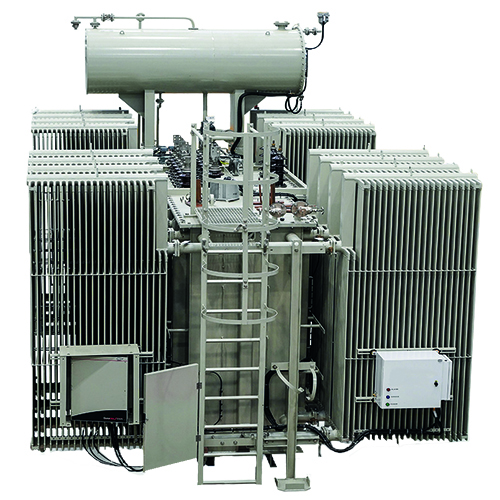
TECHNICAL DATA
Voltage Range: Up to 20kV
Power Range: Up to 10MVA
Core: The magnetic circuit is core-type with mitered joint. M5, MOH or M4 grain-oriented, magnetic steel is commonly used.
Windings: The windings may either be copper, aluminium upon the customer’s request. Low voltage windings are always failing windings in these transformer sizes. Fail windings are mechanically extremely strong, which is important in transformers for converter duty. An earthed screen is installed between the primary and
secondary windings.
Cooling: HVDC systems often run close to their capacity, a highly sophisticated cooling system for HVDC converter transformers is the most economical solution. It applies more efficient DC motors which are speed-controlled, cutting down both noise level and low losses. In the operation mode maximum cooling, it extends the transformer’s lifetime by reduced aging. It is preferred to use directed oil flow, granting that the cool oil is led by a predetermined, optimum path through the core and windings, reducing both size of the active part and the cooling system.
Tank: The tank is cylindrical-shaped with a flat cover, which can withstand the mechanical strength tests under vacuum pressure and positive pressure. On its inner wall, aluminium shielding or cooper shielding is applied.
Product Standard: IEC 60076, IEC 61378-1, DIN
EN 61378-1:2012-05; VDE 0532-41:2012-05, DIN ISO9001:2008
APPLICATION
- Offshore Wind Power
- Power Transmission
- High Voltage Distribution Lines
- To Separate Voltage Regulation Units
- Aircraft DC Bus Power
- Business Aircraft
- Local & Business Jets
- Aircraft used in military
ADVANTAGES
- Fewer copper losses. (The transformer can be made more ideal with a much higher magnetizing inductance and no air gap.)
- The output voltage ripple is less.
- Due to much larger magnetizing inductance lower active device peak current

